Tuesday, January 14, 2014

Out-of-the-Box Tweeter Enclosure

If woofers can be boxed in, ported and transmission lined, can the same be done with a tweeter? You betcha!
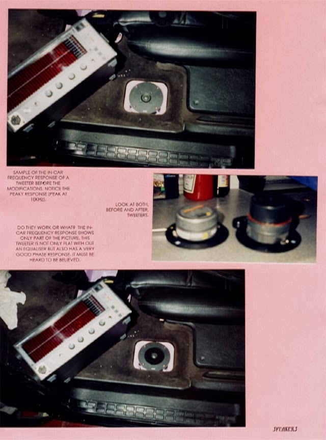
As it should be evident from looking at the installation book of the British van I built with Paul Richardson, I like modifying tweeters. This time, I would like to share the diagrams that I created for one of the most famous competitors in the circuit ever. These modifications are based on a Morel tweeter with a built-in aperiodic enclosure and a third magnet designed to short the magnetic field.  

illustration of a cut off of a dome tweeter with Aperiodic enclosure behind the dome and double magnets shorted with a third magnet.
Illustration of original tweeter with aperiodic enclosure
and double magnets shorted with a third magnet.
Not satisfied with already having a tweeter with an actual fancy enclosure behind the dome, I had to push performance beyond the normal, if an aperiodic could be considered normal. 
Over the years, I have come to trust the power handling ability and reliability of the larger Dynaudio and Morel dome tweeters. Focal tweeters have a smaller voice coil which limits how far you can push power handling. This is important when working on an enclosure that can't normally be reversed after being applied to an expensive tweeter. 
My own home system tweeters use a small transmission line. As a result, their transparency is incredible. They just do not sound like the usually euphonic Dynaudios. Mine are much faster and transparent. They almost resemble ribbons. At times, it even seems as if the tweeters have completely turned off; a characteristic also noticeable when using the stupidly expensive diamond-dome Accutons
But my transmission line is a little too long for a car. To gauge what I am attempting to describe, consider the fact that the Morels here described are already larger than most midrange speakers. 

illustration of the cut-off of a tweeter after enclosure modifications
Modified tweeter with extended enclosure 
Carefully, I drill the back of the chamber making sure to not damage the magnets. A Unibit step drill comes in handy here. All drilling must be done slowly and with lots of sticky tape to try to prevent all metal shaving from going into the tweeter. In fact, I normally remove the dome and place a protective cover over the magnetic gap. I like using double sided tape that is flexible and very sticky. 
Applying this protective tape is a little difficult with tweeters with ferrofluid with in the voice coil gap, but this never stopped me. I have been known to ask the factory for extra ferrofluid for after the surgery. 
Yes, by now, your manufacturer's warranty is gone. As if this was not enough, you are doing the mods at your own risk as I am not doing them for you. 
I look for a rigid tubular shape of approximately the same internal diameter as the inside chamber within the tweeter to extend the cavity. Aluminum pieces are always welcomed. This outside tube will have to be capped and adhered to the back of the tweeter. A slightly larger diameter is preferable to a smaller one to prevent the creation of a highly diffractive edge midway through the final cavity. 
How you do this portion of the project will depend of the circumstances and your imagination. The only thing that is most important is that the connection between cavity and tweeter must be as rigid as possible. A vibrating rear extension will defeat the point of the exercise. 
illustration of a hand cleaning a window making it more transparent
Better Transparency
I like applying felt to all internal surfaces. If possible, I try to insert felt into the tweeter's old chamber as well. Just make sure that the dome will not touch the felt during play. I suggest getting the felt from art and craft suppliers like Michael's. make sure to dedicate enough time to ensure this process goes well. Think more like a Swiss watch maker than Joe Butch at your local mechanic's shop. Finally, get a little bit of fiber glass that can be stuffed within the extension and even within part of the old cavity. How much fiberglass? Enough to ensure that midrange energy that travels towards the back of the tweeter significantly drops in amplitude before it makes it back to the front.
The whole idea behind this mod is that normal tweeters create rear pressures that hit the solid components behind the dome and then return and actually cross the dome to become audible. These distortions thus exhibit a lag in time and are asynchronous with the music. Typically, the lower the mass of the dome, the more susceptible the tweeter is to this effect. With a chamber that prevents much of this reflected pressure from making it back to the dome, the tweeter is left playing sound in response to voice coil impulses only; which is how it is supposed to operate. In a nutshell, the sound is very transparent after this modification. The only caveats are that this mod is not for first timers and that experimentation is acceptable. Without enough experience altering speakers, you may destroy your first expensive pair. 
Moreover, I have tried to model the right levels of felt and volume of additional cavity by using the same formulas as with woofers but the results are unreliable. The main reason why is that the dimensions associated with this exercise are much smaller than when dealing with woofers. So, I have learned to trust experimentation as a way to fine-tune the components. Again, if in doubt, don't start the project. 
I hope that you have found the idea useful. If you do not get the urge to modify a tweeter, at least you now know that you can treat them like you would other larger woofers.

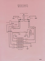
scan of installation book from British van that I helped build
Modifying a tweeter;
circa 1996

scan of installation book from British van that I helped build
Testing the outcome


Sunday, January 12, 2014

Sound-off Bullying - Poetic Beginning to a Great Run

Sound-offs can be both fun and stressing. But in all cases, bullying is unmerited. My advice, don't sink to their level. Like Chuck, take the high road instead.
International Auto Sound Competition Association Logo
International Auto Sound
Challenge Association
This is a short story of an IASCA Eastern regional event my team and I attended around 1995. Exactly when in 1995? I can't remember. So, don't mind my complete inability to remember the precise date; these events happened a long time ago. In any case, the essence of the narrative has nothing to do with time. It is all about the beginning of something awesome. 
Chuck Barbosa, now a serious Kansas City SWAT officer, was once a lost audiophile punk like me. One day, I convinced him to enter one of the most challenging shows in the US. Prior to working together, he had not had much luck at big venues; so Chuck was not too excited. But he obliged in the end.

Battered Spirit on Saturday Morning
On the morning the first day of the event, Chuck was finishing detailing his car when a famous competitor approached him. “Nice car” he said. “What class are y'all in?” Chuck competed in Amateur 251 to 500. “Damned boy, if I was you I'd stop cleaning the car and start tuning. Do ya know that red truck over there? That truck is gonna whoop you boy!”. And after pointing at his teammate's red Florida Mazda he walked away smirking and shaking his head. Needless to say, Chuck was devastated.
When Chuck told me, I replied “So what? What do you worry about? If they are better, you’ll loose any way. But they are not the judges. You just do your best and leave the rest to the real judges. The guy was just trying to intimidate you. Don’t pay attention.
I had known this guy for a few seasons but he didn't know much about Chuck and what we had done with the car. He was therefore talking out of his rear.
Chuck decided to trust on our preparation and did a really good job presenting the car.

Award Anxiety Sunday 
Trophy time arrived. Those were very competitive events when plenty of good cars battled for the last few points. Being that his new system was being day-viewed, we had no idea what to expect.
Fifth place was called. Then came fourth place. Third place went to the very good red Mazda truck. Chuck feared the worst and begun to walk away. Second place went to another impressive car.
Totally numb, Chuck didn't recognize his name when called for first place. “That’s you Chuck” everyone who knew him yelled. His smile couldn't grow any bigger. The whole thing erupted into an applause frenzy. Many people knew Chuck's incredible dedication and his previous lack of success.
Still floating, Chuck once again missed his name as Best of Show Amateur winner. It could not get any more surreal! He was finally on his way to becoming one of the most decorated sound-off competitors in the nation.

Sweetness
As soon as the last trophy was awarded, I asked Chuck, who was still glowing, to follow me with his two trophies. We walked towards the guy and, after congratulating him for his trophy, I followed my smile with "I came to introduce you to my new protegee. Meet Chuck".


The following are a few old pictures and a video of how Chuck's car looked at the end of the 1995 season (I will discuss the features in a future post): 


Photo image of the outside of the car (with the engine compartment opened) of Chuck Barbosa's Red Laser as it stood during the winter storage at the end of 1995 and beginning of 1996.
Outside of the Red Laser
during winter storage
Photo image of the outside of the car (with the hood opened) of Chuck Barbosa's Red Laser as it stood during the winter storage at the end of 1995 and beginning of 1996.
Vehicle exterior as it looked
at the end of the 1995 season

Photo image of the engine of Chuck Barbosa's Red Laser as it stood during the winter storage at the end of 1995 and beginning of 1996.
Lots of chrome and 3/8" acrylic

Photo image of the engine compartment of Chuck Barbosa's Red Laser as it stood during the winter storage at the end of 1995 and beginning of 1996.
Engine compartment


Photo image of the right open door with speaker grills of Chuck Barbosa's Red Laser as it stood during the winter storage at the end of 1995 and beginning of 1996.
Right door with midbass grills


Photo image of the right open door without speaker grills of Chuck Barbosa's Red Laser as it stood during the winter storage at the end of 1995 and beginning of 1996.
Right door with grills removed


Photo image of the front interior showing the very small kick panel in Chuck Barbosa's Red Laser as it stood during the winter storage at the end of 1995 and beginning of 1996.
Front-interior
with very small kick panels


Photo image of the front interior showing the motorized CD changer and head unit in Chuck Barbosa's Red Laser as it stood during the winter storage at the end of 1995 and beginning of 1996.
Front-interior with motorized
globe box and head unit


Photo image of the rear interior showing the power distribution panel behind the seats, the ODR system inside the motorized rear seats, and the amp rack being motorized upwards in Chuck Barbosa's Red Laser as it stood during the winter storage at the end of 1995 and beginning of 1996.
Fuse distribution behind the
motorized rear seat


Photo image of the rear interior showing the rear seat area after being motorized back into position in Chuck Barbosa's Red Laser as it stood during the winter storage at the end of 1995 and beginning of 1996.
Closed rear seat


Photo image of the rear hatch area showing the woofer box, the battery rack and the amplifier rack being motorized up in Charles Barbosa's Red Laser as it stood during the winter storage at the end of 1995 and beginning of 1996.
Rear hatch area
with amp motorization,
woofer box and
battery compartment


Photo image of the rear hatch area showing the woofer box, the battery rack, the motorized amplifier rack in the down position and the rear seat with the ODR system after being motorized open in Charles Barbosa's Red Laser as it stood during the winter storage at the end of 1995 and beginning of 1996.
Rear hatch area
with amp rack closed and
motorized rear seat
with ODR system


Friday, January 10, 2014

Low Stage Part 01 - Two Speakers

photo of a tweeter custom installed over the "A" pillar of a vehicle.
Tweeters on "A" pillars
Is your car audio's sound-stage low? Are you being told to place tweeters on the "A" pillars? Do high highs fix height?
If you have height problems, you are not alone. Most systems have height problems. Unfortunately, just as many are patched with tweeters up high. The argument is that you need speakers at eye level to fix height problems. The pundits further argue that high frequencies are responsible for height. Wow!
photo image of pink Hello Kitty band-aid box
Hello Kitty Band-aid
This reminds me of a time when, standing behind a shameless retail salesperson, I heard him tell a consumer that a woofer needed a port to breath or else die. Can you imagine a woofer being slowly chocked to death every minute of every day, whether being played or not? Clueless!
Needless to say, tweeters placed high don't address the fundamental problem. Instead, such attempts equate to no more than a Hello Kitty Band-aid. They are cute. Let me expand.
I once built an award winning truck that had waveguides underneath the front seats. The horn mouths were located right behind the front passengers' Achilles-heels with the horns firing forward towards the front of the car; where the pedals are located. In other words, they were right over the carpet's floor and aimed away from the listener.
line drawing illustration of car audio waveguides installed under the seat
Waveguides under the seat
But even under this very unusual scenario, there was no problem with either stage height or high frequency loudness. The only problem was that for a few early shows, judges struggled to score the vehicle because there were no visible speakers anywhere. And let me tell you, you never want to baffle judges. You want to impress them instead. And once the word got out that the speakers were horns and that they were being used in such an incredible manner, the scores jumped immediately.
This does not mean that placing a speaker in any one location is a bad thing. It is just that placing them there does not solve the fundamental problems behind the psycho acoustical effect of a lower stage.
To understand the issues at hand and the potential solutions, I will have to cover several aspects of acoustics; more than I would like to do in a single article. I will therefore break it into parts. My goal is to be able to clearly explain one concept at a time.

Not a Point Source
Two Way Second Order Crossover
The fact is that (1) all non-coincident systems deploying multiple drivers exhibit radiation lobes in the vertical plane around the crossover frequency. (2) But these lobes are not aligned with the design's central axis. Instead, a Polar Axis tilt results. This tilt is measured in degrees.

In simpler terms, this means that every time you use two speakers to play the same frequency their combined output will create areas of cancellation (destructive interference) next to areas of cooperation (constructive interference). Moreover, the resulting patterns of interaction are not symmetrical; they tilt more towards one of the speakers.
To visualize these concepts, look at the following illustration.
image of the sound pressure measurement from a two way speaker system with a 2nd order crossover at 2200 Hz
Sound wave measurement for a typical two way system
Two speakers, a tweeter and woofer, are surface mounted above one another as it's commonly done in home speakers. To channel high frequencies to the tweeter and low frequencies to the woofer, a second-order or 12dB/Oct crossover set at 2.2 KHz is used between the two speakers. Measurements of the acoustic pressure waves are then taken at 2.2 KHz. The resulting measurements clearly show two sets of waves; one for the tweeter and one for the woofer. Dark areas represent low pressures while white areas show high pressures.
Now direct your attention to the image below. A listener with his ear placed at the tip of the red arrow would hear most of the 2.2 KHz sound as coming mainly from the tweeter. The sound would be loud and relatively clear depending mostly of the quality of the tweeter. At this point, any attributes of the woofer are less relevant. Again, the white portions of the wave represent high pressure portions of the wave.
image of a listener focusing on a high pressure area of the sound pressure measurement from a two way speaker system
Listener focused on high pressure area

Next, look at the tip of the red arrow below. There, the listener would hear most of the 2.2 KHz sound as coming from the woofer. The dark area represents the low pressure of the wave as it radiates from the speaker. It is important to note that low pressure does not mean that loudness is low. The perceived sound would be just as loud as with the example above. This is because sound is made from two halves; low and high pressure halves. The change between these periodically repeated halves is what we hear. In this case, the quality of the sound would be mostly dependent of the quality of the woofer.
image of a listener focusing on a low pressure area of the sound pressure measurement from a two way speaker system
Listener focused on low pressure area

 Finally, look at the next arrow pointing at the middle area where the two waves interact. A close analysis shows that the tweeter's wave above is at a low pressure stage while the woofer's wave below is at a high pressure stage. Subsequently, the arrow's head is placed over an area of cancellation. In this case, gray means no sound.
image of a listener focusing on the cancelation area of the sound pressure measurement from a two way speaker system
Listener focused on cancellation area

The area between the two waves actually beams outwardly from the speaker and angles down from the center axis. This is a cancellation beam and is highlighted below. A listener on this axis would hear the effect of two waves trying to cancel each other at 2.2 KHz. 
image of an acoustic lobing graphic over a sound pressure measurement from a two way speaker system
Acoustic Pressure and Lobing Graph

This now takes us to the typical dispersion pattern graph as is commonly used by acoustical engineers:
graphical illustration of a lobing pattern resulting from the use of a second order crossover with speakers placed with their acoustical centers four inches from each other

The fundamental problem that all these graphs and images are attempting to illustrate is that the cancellation effects that result from using two speakers distort and destroy any illusion of a realistic sound. As we will see later, this distortion is also behind the height problems experienced by many car guys. 
I will take us deeper on the subject on a future post. Until then, happy listening!


A video showing all components of a two way system:

Wednesday, January 8, 2014

Electrifying Reality

Why is it that the first thing nurses do when you land at the hospital is to insert a conduit for intravenous fluid? What's the deal with the Salty Water?
The physics-loving geek within me was thrilled with Electric Universe: How Electricity Switched on the Modern World by David Bodanis.
Despite having spent a large portion of my professional carrier on the subject, this book helped me understand a few new things about electricity. More specifically, it covers a lot of new information about the electric system within our bodies.
The whole book is nonetheless about pure physics fun. Because of it and the fact that it isn't written in fable form, it is not for everyone. On the other hand, physics students or those who love the quantitative side of nature will find this to be a must read. Yes, those who love tinkering with their audio system are also included within the latter group. Enjoy!

Monday, January 6, 2014

A Little Gauss: A Calculator & the Law

Playing with coils? Have you ever wondered the strength of a magnetic field at a given frequency? Well, just in case that you need to geek-out, here is a Gauss calculator I have used in the past when playing with coils.

screen shot of an excel document with the formula needed to calculate Gauss
Gauss Calculator for Excel
And what a better way to get to understand a little Gauss Law as it applies to conductors than to watch Professor Ramamurti Shankar from Yale explain it.


And for those who wish to look at it a little closer, then here's the video's transcript:

          830: FUNDAMENTALS OF PHYSICS II
          Lecture 4 - Gauss's Law and Application to Conductors and Insulators [January 20, 2010]
          Chapter 1: Derivation of Gauss's Law [00:00:00]
          Professor Ramamurti Shankar: Let's start with a brief recall of Gauss's Law...  
          (read the rest here)

For the complete course, visit Yale's PHYS 201: Fundamentals of Physics II web page.

Saturday, January 4, 2014

Best Sound in a Vehicle

Can I brag? How much? Can I brag a lot? Is it bragging if performance is evidenced by the facts and certified by experts?
These are two videos of the best and last installation I did. Working with British super star Paul Richardson, this was my farewell from the installation bay. And it all ended with a massive bang. Paul and I cleaned house.
But now, all that's left is the memory of it. As melancholy travels through my soul, I am trying to reconstruct what can no longer exist through this blog post. I know that I will never again hear the van's incredible sound. But be certain that, at least in my mind, I will replay the songs I remember.
I also know that we tend to idealize what's not material or tactile anymore. But I am fine with an enhanced delusion of what the van was. During its time, nothing came anywhere close to it. Not on install. And especially not on sound.
As a well regarded sound judge who has continued to audition and evaluate the best cars out there, I am allowed to claim that this van was the best ever. Surely there were some fantastic cars like Gary Bigg's many versions of his stupendous Regal, Chad Klodner's majestic Mustang and many others. But I will hold my ground. The ginormous stage made one feel like being seated in the middle of Royal Festival Hall in London. The musical clarity defied even the best home systems. And oh, the low noise. The system was eerily quiet during all musical playback. Textures were delicious and tonality rode right on the line between too sweet and precise. Finally, the psycho-acoustics possible were incredible. Turning the head towards the rear would completely collapse the sense of space. Turning back towards the front would be like launching the Titanic a few feet from your face. It was most certainly a visceral experience. You would forget that you were within a space.
I am afraid that nothing I say will make justice to its performance. So, I will regress to the point of this post. Sharing the videos. The first video offers a short tour of the installation.

The second presents the installation book created for the van. Do keep in mind that in those years, computers did little more than act as typewriters.

For those who like to click through dozens of images, these are the scans from each page: